INA226 Overvoltage Warning Light & Sound Using Arduino
2026-06-05 | By Ron Cutts
License: GNU Lesser General Public License Current Microcontrollers Power Supplies Voltage Arduino ESP32
In this tutorial, we will learn how to make an overvoltage warning using the INA226 module, an LED, and a Piezo buzzer module.
If the voltage is below 6V, the green LED will glow; if the voltage is above 6V, the red LED will glow, and the piezo buzzer will beep. Voltage can be set according to your needs.
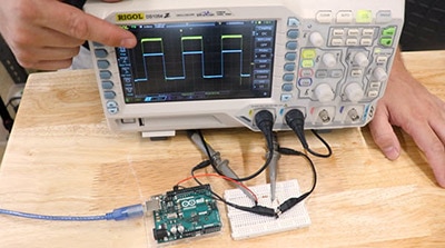
Watch the video!
Learn more about Visuino: What is Visuino
What You Will Need
Arduino UNO or any other Arduino board
INA226 module
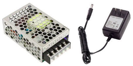
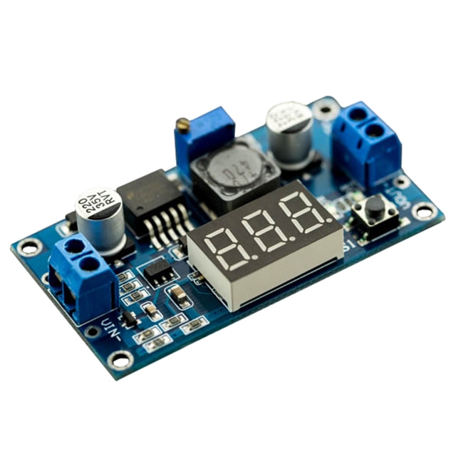
(Optional) Power Supply to do the test
Visuino software: Download here


The Circuit
Connect the INA226 Module pin [SCL] to Arduino pin [SCL]
Connect the INA226 Module pin [SDA] to Arduino pin [SDA]
Connect the INA226 Module pin [VCC] to Arduino pin [5v]
Connect the INA226 Module pin [GND] to Arduino pin [GND]
Connect the Power Supply (or any Voltage source that you want to monitor) positive pin (+) to the INA226 Module Pin (V+)
Connect the Power Supply (or any Voltage source that you want to monitor) negative pin (-) to the INA226 Module Pin (V-)
Connect Arduino Digital Pin [2] to a 1k ohm resistor and connect the other side of the resistor to the Red LED positive pin [+]
Connect the Red LED negative pin [-] to GND
Connect Arduino Digital Pin [3] to a 1k ohm resistor and connect the other side of the resistor to the Green LED positive pin [+]
Connect the Green LED negative pin [-] to GND
Connect Arduino Digital Pin [4] to the piezo buzzer module pin [S]
Connect Arduino Pin [VCC] to the piezo buzzer module pin [+]
Connect Arduino Pin [GND] to Piezo buzzer module pin [-]


Start Visuino, and Select the Arduino UNO Board Type
Start Visuino as shown in the first picture. Click on the "Tools" button on the Arduino component (Picture 1) in Visuino. When the dialog appears, select "Arduino UNO" as shown in Picture 2


In Visuino, Add Components
Add "INA226" component
Add "Digital Multi Source" component
Add "Digital Inverter" component
Add "Play Frequency Tone" component


In Visuino Set Components
Select "DigitalMultiSource1" and in the properties window set "Output pins" to 3
Double click on the "PlayFrequency1" and in the Elements window, drag "Play Tone State" to the Left side and in the properties window, set "Frequency (Hz)" to 20
Close the Elements window
Select "VoltageCurrentPower1" and in the properties window expand "Alerts">:Limit" and set "Above" to True
Now expand "Alerts">:Limit">"Bus Voltage" and set "Value (V)/(A)/(W)" to 6 (or any other Voltage value that you need)


In Visuino Connect Components
Connect "VoltageCurrentPower1" pin I2C (Control) to Arduino Pin I2C (In)
Connect "VoltageCurrentPower1" pin Limit (Out) to "DigitalMultiSource1" pin (In)
Connect "DigitalMultiSource1" pin (0) to Arduino digital pin (2)
Connect "DigitalMultiSource1" pin (1) to "Inverter1" pin (In)
Connect "Inverter1" pin (Out) to Arduino digital pin (3)
Connect "DigitalMultiSource1" pin (3) to "PlayFrequency1" > "Play Tone State1" pin (In)
Connect "PlayFrequency1" pin (Out) to Arduino digital pin (4)


Generate, Compile, and Upload the Arduino Code
In Visuino, at the bottom, click on the "Build" tab, make sure the correct port is selected, then click on the "Compile/Build and Upload" button.

Play
If you power the Arduino module, the green LED will glow, and if the voltage connected to the INA226 module is above 6V, a red LED will glow, and a buzzer module will beep.
Congratulations! You have completed your project with Visuino. Also attached is the Visuino project that I created for this tutorial. You can download it and open it in Visuino: https://www.visuino.eu